
This guide covers the complete, correct installation of a sight glass—from pre-installation checks through validation—following industrial best-practice standards. Whether you're a maintenance technician, process engineer, or working in regulated food, pharma, or chemical industries, these techniques ensure leak-free performance and compliance.
Key Takeaways
- Installation complexity scales with connection type: threaded is straightforward, flanged and tri-clamp require greater precision
- Verify material compatibility, pressure/temperature ratings, and flow orientation before mounting
- Match the seal to the connection: PTFE tape for threaded, O-rings for flanged, sanitary gaskets for tri-clamp. Never over-tighten.
- Complete post-installation validation (visual check, pressure test, leak check) before system startup
- For regulated industries, confirm compliance with FDA 21 CFR 110.20, 3-A Standard 65-01, or USDA standards
Sight Glass Installation Overview
Sight glass installation follows a defined sequence: pre-installation verification → site preparation → mechanical mounting and sealing → system integration → validation. Skipping steps creates problems that surface only under operating conditions—often catastrophically.
Time expectations vary significantly:
- Simple threaded bullseye sight glass: 30-60 minutes
- Flanged inline sight glass with isolation valves: Several hours, requiring a second technician and full system depressurization
The difference lies in connection complexity, system accessibility, and whether you're integrating into existing pressurized lines or building new ones.
Prerequisites and Sizing Considerations
Before touching tools, verify these system conditions:
Safety and access requirements:
- Line is fully depressurized and drained
- Isolation valves are closed and locked out (OSHA 29 CFR 1910.147 mandates lockout/tagout)
- Installation site has adequate clearance for viewing and maintenance
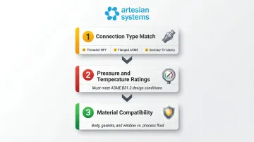
Compatibility across three critical dimensions:
- Connection type match — Threaded NPT, flanged ASME, or sanitary tri-clamp
- Pressure/temperature ratings — Must meet or exceed system design conditions per ASME B31.3
- Material compatibility — Body, gaskets, and window must resist the process fluid
Non-negotiables:
- Never install a sight glass rated below system operating pressure
- Do not use glass-body sight glasses in food/pharmaceutical applications where FDA 21 CFR Part 110.20(b)(5) prohibits breakable glass over exposed product
- Do not proceed if the system cannot be fully isolated
Chemical compatibility: Consult the Parker O-Ring Handbook (ORD 5700) for elastomer/seal compatibility with 1,800+ chemicals, or manufacturer-specific resistance tables for body materials.
Tools and Materials Required
Once system conditions are confirmed, gather the following before starting.
Essential toolkit:
- Strap wrench or calibrated torque wrench (never use pipe wrenches on plastic bodies)
- PTFE thread seal tape or pipe sealant for NPT connections
- Gaskets or O-rings matched to process fluid
- Flange bolts and hardware to specification (for flanged types)
- Isolation valves (if not already in line)
- Cleaning rags and PPE appropriate to fluid
Required materials vary by connection type:
| Connection Type | Required Materials |
|---|---|
| Threaded NPT | PTFE tape, strap wrench, plastic nipple adapters (if connecting to metal pipe) |
| Flanged | Matched companion flanges, O-rings (usually included), torque wrench calibrated to spec |
| Sanitary Tri-Clamp | Correct clamp, ferrule gasket (PTFE, EPDM, or silicone matched to fluid), torque setting per ASME BPE SG-4.2 |
Never substitute generic gaskets in sanitary or high-pressure service. Artesian Systems offers tri-clamp sight glasses in 1.5" to 6" sizes with borosilicate or polycarbonate windows. Each unit ships with FDA 21CFR177.2600-compliant gaskets in PTFE, EPDM, Viton, or BUNA-N, so material compatibility is pre-verified before installation begins.
Step-by-Step Installation
Installation shortcuts—particularly skipped gasket checks, over-tightening, or missed alignment steps—account for the majority of sight glass failures. Follow each step in order.
Step 1: Prepare the Installation Site
Shut down and isolate:
- Depressurize and drain the line
- Lock out isolation valves following LOTO procedures
Inspect and clean:
- Examine the port or pipe segment for corrosion, debris, or old sealant
- Clean port faces or pipe threads completely
- Confirm port size and thread spec or flange rating matches the sight glass
Step 2: Mount with Correct Sealing Method
For threaded connections (NPT):
- Apply PTFE tape to male threads starting two threads back from the end, wrapping in the direction of the thread spiral
- Hand-thread the sight glass in place
- Tighten with a strap wrench—typically one-quarter turn past hand-tight
- Never use pipe wrenches or locking pliers on plastic bodies—direct metal-to-plastic threading causes mechanical stress ruptures; Plast-O-Matic specifies "always use plastic nipples between metal fittings"
For flanged connections:
- Center the sight glass body between companion flanges (O-rings usually included)
- Align bolt holes
- Tighten flange bolts in a cross-pattern (alternating opposite bolts) per ASME PCC-1 guidelines: 30% of final torque, then 60%, then 100%
- Typical final torque: 25-30 ft-lbs for most flanged sight glasses
For sanitary tri-clamp connections:
- Place the correct gasket (EPDM, silicone, or PTFE matched to process fluid and CIP chemical compatibility)
- Bring ferrule faces together squarely
- Tighten clamp to specified torque per size and gasket type:
| Clamp Size | EPDM (Dry) | PTFE (Lubricated) |
|---|---|---|
| 1.5" | 3 Nm | 10 Nm |
| 2"-3" | 4 Nm | 15 Nm |
| 4" | 5 Nm | 20 Nm |
| 6" | 10 Nm | 30 Nm |
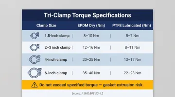
(Source: Aseptconn AG Torque Guide based on ASME BPE SG-4.2)
Do not exceed specified torque values. Stop at the defined turn count past hand-tight; going further risks gasket extrusion and seal failure.
Step 3: Confirm Orientation
Flow indicators (inline type): Can be installed horizontally or vertically per manufacturer specs
Level indicators: Must always be mounted vertically to maintain accurate readings
Directional flow sight glasses: Confirm flow direction matches the arrow or inlet marking on the body
Refrigeration applications: Install on the liquid line downstream of the receiver and drier, upstream of the expansion valve—standard component sequence for moisture and charge monitoring
Step 4: Integrate with Isolation Valves
Once orientation is confirmed, connect the sight glass to its isolation valves before returning the system to service.
For level indicators:
- Connect top and bottom ports to the tank with true-union ball valves
- Allows removal for cleaning without draining the vessel
For inline types:
- Confirm no goosenecks or trapped sections in connecting tubing that could cause false readings
- Reconnect all tubing, tighten fittings
- Verify no kinks or excessive stress on the sight glass body from adjacent pipe runs
Step 5: Slowly Re-Pressurize the System
Bring pressure up gradually. A sudden surge to full operating pressure stresses seals and can dislodge improperly seated gaskets.
- Open isolation valves incrementally, not all at once
- For transparent window types, watch seal interfaces closely during pressure build-up
For drip-type sight glasses (lube oil systems):
- Manually prime the assembly to purge air before closing the system
- Ensures accurate fluid reading from startup
Post-Installation Checks and Validation
Visual and structural inspection:
- Check all seal points (threaded interfaces, flange faces, tri-clamp seats) for gaps, misalignment, or unseated sealant
- Confirm the sight glass body is not under mechanical stress from pipe misalignment
Functional testing:
- Slowly bring the system to operating pressure while monitoring for leaks
- For flow indicators: Verify visible fluid movement or flutter device deflection
- For level indicators: Confirm fluid level matches independent measurements
- For drip-type sight glasses: Count drops per cycle—6-10 drops per pump cycle is typical for mechanical oil pumps
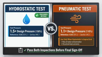
Once functional checks pass, confirm pressure integrity before sign-off. ASME B31.3 defines two accepted methods:
Leak testing per ASME B31.3:
- Hydrostatic test at 150% of design pressure (Section 945.1)
- Pneumatic test at 110% of design pressure (Section 345.1) only when hydrostatic testing is impractical (e.g., when water contamination of the process fluid is a concern)
Indicators of incorrect installation:
- Weeping or dripping at seal interfaces → under-tightened or misaligned seals
- No visible fluid movement in flow indicator during known flow — likely a blocked or air-locked assembly
- Cracked or deformed body immediately after tightening → over-tightening (especially plastic bodies)
Resolve any failures before documenting the installation as complete — in regulated industries, a signed pressure test record is standard practice and may be required for audit compliance.
Common Installation Problems and Fixes
Leaking Seals After Pressurization
Fluid weeping from a threaded connection, flange face, or tri-clamp joint during or after initial pressurization usually points to one of these causes:
- Insufficient or incorrect thread sealant
- Misaligned flange faces
- Gasket material incompatible with the process fluid
- Tri-clamp not seated squarely before tightening
To fix: depressurize and drain the line, then inspect all seal interfaces. Replace gaskets if deformed or chemically incompatible, reapply thread sealant on threaded connections, and re-seat and re-torque flanged or tri-clamp connections as needed.
Never attempt to tighten fittings under pressure.
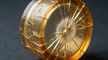
Cracked or Deformed Body After Installation
Cracking, deformation, or crazing on plastic or acrylic sight glass bodies shortly after installation typically has three root causes:
- Over-tightening with inappropriate tools (pipe wrenches, locking pliers)
- Direct metal-to-plastic threading without a plastic nipple adapter
- Exposure to incompatible process fluid or CIP cleaning chemical
Material compatibility matters here. Acrylic (PMMA) is vulnerable to methanol, acetone, MEK, MIBK, and isopropanol, while polycarbonate suffers environmental stress cracking with benzene, chlorobenzene, or acetone. Always verify compatibility before specifying a sight glass material for your process.
To fix: replace the damaged unit, then correct the installation approach — use a strap wrench on plastic-body types, insert a plastic nipple between metal pipe threads and the sight glass body, and confirm chemical compatibility with both process fluid and CIP solutions.
Inaccurate or No Fluid Reading
When a sight glass shows no movement, or the level reading doesn't match actual system conditions, the cause depends on the sight glass type:
- Level indicators: A gooseneck or trapped section in the connecting piping blocks fluid communication
- Drip-type sight glasses: Air in the line hasn't been purged
- Flow indicators: Unit installed with flow running against the indicated direction
For level indicators, inspect connecting piping for elevation changes or traps. For drip-types, manually prime the pump and purge air through the top port before sealing. For flow indicators, confirm orientation against the manufacturer's flow-direction markings and reinstall if reversed.
Pro Installation Tips
Sequencing and material selection:
- Procure gaskets, sealants, and sight glass materials before installation day
- Match materials to both process fluid and CIP/sterilization chemicals—critical in food, beverage, pharmaceutical, and hemp extraction
For regulated industries:
- Source sight glass components with FDA 21CFR177.2600, 3-A, or USDA compliance documentation
- Artesian Systems manufactures sanitary tri-clamp sight glasses with borosilicate glass windows (operating range: -40°C to 500°C, 150 PSI) and FDA/3-A/USDA-compliant gaskets—component documentation is included to support equipment qualification records
Isolation valve planning:
- Install true-union ball valves on inlet/outlet sides of inline sight glasses and top/bottom ports of level indicators
- Allows isolation, removal, cleaning, or replacement without shutting down the entire line (skipped more often than not on first install—and almost always regretted at the first maintenance event)
Documentation and sign-off:
- Record sight glass model, connection size, gasket material, torque values, operating pressure range, and installation date in maintenance log
- In regulated environments, this documentation is part of equipment qualification records required for audits
- Photograph the installed assembly before re-enclosing panels
Conclusion
Sight glass installation quality directly determines monitoring reliability, seal integrity, and system safety. An incorrectly sealed or oriented sight glass either fails under pressure or produces misleading readings that can trigger contamination events or batch losses downstream.
Thorough preparation covers the essentials: materials compatibility verification, compliance documentation, and lockout/tagout procedures. Precise execution — correct torque, the right sealing method for each connection type — followed by thorough post-installation validation ties it together.
The 30 minutes spent validating a proper installation saves days of unplanned downtime and thousands of dollars in lost production.
Frequently Asked Questions
Where is the best place to install a sight glass in a refrigeration system?
Install on the liquid line, downstream of the receiver and drier but upstream of the expansion valve. This standard location allows operators to see refrigerant state (bubbles indicate low charge) and confirms the drier is functioning correctly.
Are sight glasses directional—which way should refrigerant flow through them?
Most refrigerant sight glasses are not strictly directional for sealing purposes, but they're typically marked with a flow arrow. Install so refrigerant flows in the indicated direction to ensure accurate moisture indicator readings and proper internal function.
Should a refrigerant sight glass be wet or dry?
A correctly charged and dried system should show a dry sight glass with clear, bubble-free refrigerant flow. Bubbles or foaming indicate low refrigerant charge or moisture contamination. A wet indicator element (if present) signals the drier needs replacement.
How does a sight glass work?
A sight glass uses a transparent window or tube connected directly to a vessel, pipe, or reservoir. The fluid level or flow state mirrors what's happening inside the system, enabling real-time visual monitoring without interrupting the process.
What causes a sight glass to leak after installation?
The three most common causes are:
- Insufficient or incorrect thread sealant on NPT connections
- Misaligned or incompatible gaskets on flanged or tri-clamp connections
- Over- or under-tightening, which compromises the seal interface under operating pressure
Can sight glasses be installed in any orientation?
Flow indicators (inline type) can generally be installed horizontally or vertically, but level indicators must always be mounted vertically to give accurate readings. Always check manufacturer orientation requirements—designs with internal floats or flutter devices are orientation-specific.